LibreCAD v2.2.0 - User Manual
This is an interim release of the of the LibreCAD User Manual and is subject to change.
The manual is based on LibreCAD v2.2.0-rc1 with a few additions. If you are using another version of LibreCAD, your mileage may vary.
Blocks
Blocks are reusable drawings of commonly used objects such as bolts, furniture, electronic components, title blocks, etc. Inserted blocks, also called instances or inserts, are composed of geometric shapes (lines, arcs, etc.), but can also include text and dimensions. Blocks can be created in the current drawing, inserted from the block library, or imported from a separate drawing file, Once inserted blocks can be used repeatedly within the drawing.
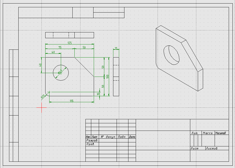
Example of the Doohickey drawing with blocks, including the page border from the Library Browser (“sheets -> A4H”) and a block imported from a drawing file (isometric view).
Working with Blocks
There are two dock widgets for managing blocks. The Block List dock for managing blocks within the current drawing and the Library Browser dock that displays a collection of blocks in the library. Both widgets allow users to insert blocks into the current drawing, but there are a couple of important differences:
Blocks inserted from the Block List:
- A block can be placed at a different locations, scale, and/or rotation angle, and also be placed in an array.
- Blocks inserted from the same block in the Block List is called an instance. If a block is inserted from the same block multiple times all instances of the block are linked. Changes to one instance of the block will be reflected in all instances of that block.
Blocks inserted from the Library Browser:
- Each block can be placed at a different location, rotation angle and/or scale.
- Blocks inserted multiple times will create a new instance of the block in the Block List each time it is inserted. After the initial insertion, the blocks will numbered sequentially (e.g. BlockName, BlockName-0, BlockName-1, …) The inserted blocks will be independent of each other.
Blocks can also be imported from a separate file and will appear in the Block List. Drawing files imported multiple times will create a new instances in the Block List and be numbered sequentially as with blocks inserted from the Library Browser.
Using the Block List
Creating a Block
Blocks can be created in the current drawing for use within the drawing. There are two ways to create a block:
From an existing object:
- Ensure the all entities for the object to be made into a block are on layer “0”.
- Select all the entities that make up the object.
- Click on the Create Block icon
.
- Specify the reference point for the block. The reference point is used to locate the object when it is inserted into the drawing.
- Provide a unique name for the new block and click OK. The new block will appear in the Block List.
- The original object can be deleted from layer “0”. The new block remains available in the Block List.
From an empty block:
- Click on the Add an empty block icon
. Provide a unique name for the new block and click OK. The new empty block will appear in the Block List.
- Select the new block in the Block List and click the Edit the active block in a separate window icon
.
- Ensure layer “0” is selected and draw the object. The drawing’s origin (0, 0) will become the reference point for the block.
- Close the new block’s drawing window and the new block will be saved.
Important
Layer “0” has a special significance. It is the default layer for new drawings. More importantly in the context of blocks, it is equivalent to “no layer”, similar in the way that color “By Block” is equal to “no specified color” or line type “By Block” is equal to “no specified line type”. Generally layer “0” should only be used when creating blocks and should be the only layer in a drawing for a block.
Pay particular attention to the Attributes when creating blocks. In addition to the specific attributes, pen attributes (Color, Width, Line Type) also include “By Layer” and “By Block”.
- Blocks with specific attributes (e.g. color set to blue, width set to 0.18 mm, etc) will retain those attributes when inserted into a drawing. The block needs to be edited to change any of the attributes.
- Blocks with the attributes set to “By Layer” will adopt the attributes of the layer they are inserted in to. The block’s attributes will change if the layer’s attributes are changed.
- Blocks with the attributes set to “By Block” will initially adopt the attributes assigned to the layer. The attributes can be changed with the Attribute tool.
Inserting Blocks
Blocks can be inserted from the Block List or from the Library Browser (see below). When inserting a block from the Block List, the Block List Tool Options toolbar is displayed:

- Block can be rotated by the specified Angle and scaled by the Factor.
- A pattern of blocks can be created by specifying the number of columns and rows in the Array and Spacing between the columns and rows.
To insert a single block:
- Select a layer for the inserted blocks.
- Select a block in the Block List.
- Click on the Insert the active block icon
.
- Set the rotation angle in the Angle field and the scale factor in the Factor field as required. (See Angles in Fundamentals and “Scale” in Modify tools for more information.) Note: Leave the Array values as “1” and Spacing values remain as “1.0”.
- Place the block at the desired location within the drawing.
- Adjust the rotation angle and scale as needed and place additional copies of the block, or press [Esc] to exit the command.
Transformations (rotation, scale) and an array can be combined in a single block insertion. The the scale and spacing is applied to the individual blocks within the array, however the rotation angle is applied to the entire array.
To insert an array of blocks:
- Select a layer for the inserted blocks.
- Select a block in the Block List.
- Click on the Insert the active block icon
- Set the rotation angle and scale factor as needed.
- Set the numbers of columns and rows in Array to create the required pattern.
- Set the column spacing. This is the distance between the insertion point of two blocks in adjacent columns.
- Set the row spacing. This is the distance between the insertion point of two blocks in adjacent rows.
- Place the block at the desired location within the drawing. The insertion point of the array is the insertion point of the lower-left item in the array (at 0 degrees rotation).
- Adjust the options as needed and place additional copies of the block, or press [Esc] to exit the command.
Note
When the Angle, Scale, Array size and Spacing are all applied to an array of blocks, the array is created as follows:
- the scale, number of columns / rows and spacing is applied to the blocks in the array, and then
- the entire array is rotated around the lower left corner of the array.
- The blocks are rotated as the array is rotated and the spacing remains as defined even if the block entities are scaled.
Using an array will treat all blocks in the array as a single block instance. Selecting one entity of the array will select the all blocks in the array. To keep instances separate, insert multiple instances from the block list or create additional copies with the “Move / Copy” tool or normal edit commands (cut, copy, paste).
Editing a Block
- Select a block in the Block List and click the Edit the active block in a separate window icon
- Edit the block as necessary.
- Close the block’s drawing window and the block will be saved and all instances of the block will be updated in the current drawing.
Saving Blocks
Blocks can be saved to a separate file and used in other drawings or added to a user-defined library. To save the block:
- Select a block in the Block List.
- Click the Save the active block to a file icon
.
- Select a file location, specify a file name and click Save.
Recommendation
When saving blocks to be added to the library it is recommended that the block’s entities be placed on layer “0” and layer “0” is the only layer in the drawing. Any additional layers in the block’s drawing will be added to the new drawing when the block is inserted. The additional layers may have unintended consequences.
Using the Library Browser
LibreCAD includes several categories of blocks in its own library; algorithm, elektro, plan/air_water, plan/architect, etc. A user-defined library can also be configured in LibreCAD.
Inserting Blocks
Recommendation
When using blocks from the library, insert a single insert from the Library Browser and then insert subsequent instances from the Block List. Inserting the block from the Block List retains the link between instances of the same block insert. If a block is edited from the Block List, all instances of the block will show the changes.
Only insert multiple inserts of a block from the Library Browser if they are to be independent.
To use blocks from the Block Library, select the block from the tree view and insert it in the drawing. Blocks inserted from the library can be rotated and scaled through the Library Browser Tool Option toolbar:

The rotation angle and the scale factor behave as they do for a block inserted from the Block List.
To insert a block:
- Select a layer for the inserted blocks.
- Select a block in the Library Browser.
- Click on the Insert button.
- Set the rotation angle and scale as needed.
- Place the block at the desired location within the drawing.
- Adjust the options as needed and place additional copies of the block or press [Esc] to exit the command.
Adding a User-defined Library
Additional parts and libraries can be added for blocks created by users, libraries downloaded from the LibreCAD wiki (https://wiki.librecad.org/index.php?title=Part_Libraries) or from other internet resources. LibreCAD can be configured to show user-defined blocks in the library browser in addition to the blocks included with LibreCAD.
The easiest method of installation, which does not require or Linux Root privileges or Windows Administrator access, is to create a new directory such as “Parts_Library” in the home directory or “Documents” folder. The path to this directory would be something similar to “/home/{Username}/Parts_Library/” or “C:\Users\ {Username}\Documents\Parts_Library\ “. Blocks and libraries can then be placed under the parent “Parts_Library” directory. The sub-directories will create categories that will appear in the tree view of the Library Browser.
Important
Do not place blocks directly in the parent directory of the parts library. Blocks must be placed in sub-directories to the parent libraries directory to appear in the Library Browser.
To include the new blocks in the Library Browser tree view, edit LibreCAD’s Application Preferences to add the path to the directory or folder with the user-defined blocks. From the menus, select Options -> Application Preferences and select the Paths tab. Type the full path to the part library, e.g. /home/{Username}/PartsLibrary/ or C:\Users\ {Username}\Documents\PartsLibrary\ , into the text-box labelled “Part Libraries” and click “OK”. Click the Rebuild button on the Library Browser dock and the new libraries will appear in the tree view.
Importing Blocks
Blocks can also be inserted from as a file from other sources. With an open drawing:
- Select File -> Import -> Block.
- Locate and select the block drawing file and click “Open”.
- Set the rotation angle and scale as needed.
- Place the block at the desired location within the drawing.
- Adjust the options as needed and place additional copies of the block or press [Esc] to exit the command.
As with inserting a block from the Library Browser, importing a block multiple times will create a new instance of the block in the Block List each time it is imported, each with a sequentially numbered block name after the initial block insert. When using blocks from external files the same layer criteria applies (i.e. layer “0”, …)
“Exploding” Blocks
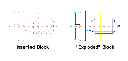
Once a block has been inserted into a drawing, it is treated a single entity and can only manipulated (moved, scaled, etc.) as a single entity. Select any one entity within the block selects the entire block. However, blocks can be disassembled, or exploded, and once exploded the individual entities making up the block can be edited. To explode a block:
- Select a block.
- Click on the Explode icon
.

Note
Once a block has been exploded it is no longer a block and cannot be treated as a single entity. If it is necessary to recreate the block, refer to Creating a Block above.