LibreCAD v2.2.0 - User Manual
This is an interim release of the of the LibreCAD User Manual and is subject to change.
The manual is based on LibreCAD v2.2.0-rc1 with a few additions. If you are using another version of LibreCAD, your mileage may vary.
Annotating a Drawing
A drawing in and of itself provides an image of what the object might look like, but it doesn’t provide a complete description of the object. Knowing the size of the object is also very important. The size of the drawn object is shown with measurements, dimensioning, and other textual information to describe the drawn object. Together, dimensions and text is called annotating a drawing.
Dimensioning an object on a drawing provides the information necessary to be able to interpret the object and ultimately create it, whether it be a building or a doohickey. Other textual information in the form of notes, symbols, call-outs, etc. provide further details for the object drawn.
Dimensioning
Dimensions are used to define length, width, height, and/or angle of a line entity, the diameter of circle entity, or radius of arc entity. A drawing’s dimensions must be:
- Accurate
- Legible
- Complete
Types of Dimensions
LibreCAD supports the following types of dimensions:
| Type | Description |
|---|---|
| Aligned | Places the dimension parallel to a line between the two endpoints of the dimension. |
| Linear | Dimension between two points from any angle of interest. The default is 0 (horizontal) and is changed via Tool Options toolbar. |
| Horizontal | Horizontal Dimension between two points. |
| Vertical | Vertical Dimension between two points. |
| Radial | Radius of an arc. |
| Diametric | Diameter of a circle. |
| Angular | Angle between two lines or linear parts of objects. |
| Leader | Not a dimension per se, but used for notes in drawings. |
Complete descriptions of the dimensioning tools and related options are found in Drawing Tools of the Reference section.
Dimensioning Appearance
A dimension consists of several parts:
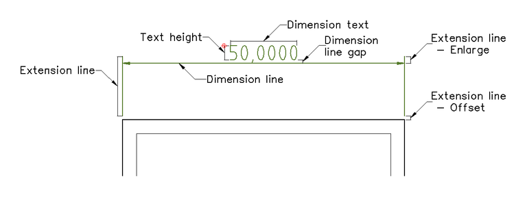
The appearance of the dimensions are configured in the Dimensions tab in the Drawing Preferences. As with many other aspects of a drawing’s setup, there are some generally accepted values for dimensioning:
| Dimension Component | mm | Decimal Inch | Fractional Inch |
|---|---|---|---|
| Dimension text height | 2.5 | .100 | 3/32 |
| Dimension line gap | 1.5 | .0625 | 1/16 |
| Extension line - Offset | 1.5 | .0625 | 1/16 |
| Extension line - Enlarge | 3 | .125 | 1/8 |
| Arrow size | 3 | .125 | 1/8 |
Note - Adjusting Dimensions for Printing
The size of each dimension component: “Text Height”, “Arrow size”, etc. should be set to the desired “real world” size in the configuration. That is to say if the desired text height is 2.5 mm when printed, the “Text Height” should remain set as 2.5 mm. If the drawing is printed full scale (1:1) the dimension text will appear correctly. However if the drawing is scaled up or down the “General Scale” needs to be adjusted accordingly. The “General Scale” is set to the inverse of the printing scale. For example, if the printed scale is determined to be 1:4, the “General Scale” should be set to 4 (4:1).
The minimum spacing between dimension lines needs to be scaled with the drawing. For example, if the drawing is 1:10, the spacing will need to be adjusted to 60 mm between dimension lines and 100 mm from the entity.
Additional information can be found in the Drawing Setup and Printing guides.
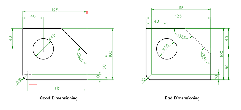
Tip - Rules for Dimensioning
A few rules will help to ensure dimensions are accurate, legible and complete:
- There should be only one way to interpret any one dimension.
- Dimension and extension lines should not cross.
- Extension lines and entity lines should not overlap.
- Provide space between dimensions to ensure legibility.
- The view that best shows an entity is the view that should be dimensioned.
- Each entity on the drawing should be dimensioned and dimensioned only once.
- There should be no need to calculate or scale a dimension of an entity.
- A dimension should be referenced to a logical origin point.
- When there are multiple lines of dimensions, the longer dimensions are to be placed outside of shorter ones.
- Except for large circles and arcs, all dimensions should be placed outside the part and spaced 10mm / 3/8” from the entity.
- Dimension circles with diameters and arcs with radiuses.
- Center lines or center marks should be used on all circles and arcs.
- Extended a circle’s or arc’s center lines and use as extensions line when possible.
- Multiple lines of dimensions are spaced uniformly with a minimum of 6mm / 1/4” between dimension lines (see note above).
- Use arrow heads or slash marks at the end of the dimension lines.
To improve legiblity, make corrections, or make adjustments after scaling a drawing, dimension labels, dimension lines and extension lines can be repositioned using Entity Handles.
Dimensioning drawings is beyond the scope of the LibreCAD User Manual, but additional resources and examples are available in LibreCAD’s wiki or elsewhere on the web.
Dimensioning Example
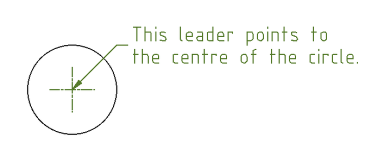
Leaders
While leaders do not dimension an entity, they are closely related to dimensioning as they are important for annotating and adding clarity to entities. Leaders provide the ability to place pointers to identify a specific area of interest when adding a note and linking it to a particulate object. Leaders take their settings from the dimension settings in Drawing Preferences.
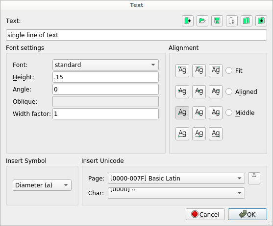
Text
Adding text to a drawing provides addition information; build notes, drawing title and related details, and so forth. Text can be added using either of the two types of text tools:
“Text”:
 |
“MText” (multi-line):
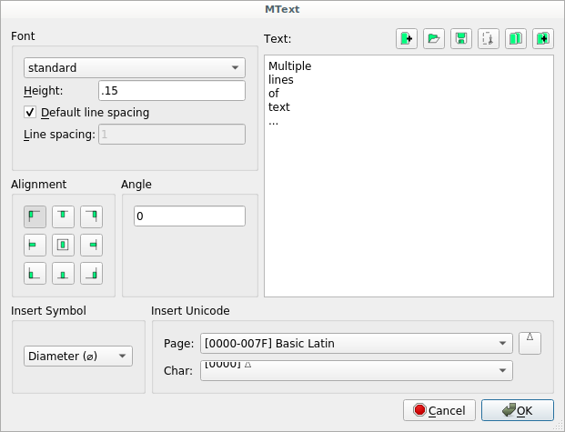 |
Both tools proved several options for the appearance and placement of text, however a couple are unique to the single-line Text tool as shown below:
| Option | Description | Text | MText |
|---|---|---|---|
| Font Settings: | |||
|
Select font for text | X | X |
|
Set font height | X | X |
|
Places text at specified angle | X | X |
|
Inactive | X | X |
|
X | X | |
|
Use default line spacing for specified font | X | X |
|
X | X | |
| Alignment: | |||
Place text aligned to handle:
|
X
X
X
X
|
X
X
X
|
|
|
Places text between specified points while
maintaining set height
|
X | X |
|
Places text between specified points while
maintaining width to height ratio (scales text)
|
X | X |
|
Places text with equidistant above and below, left and
right of text as defined by text box
|
X | X |
| Insert symbol | Insert predefined symbol (Diameter, Degree, Plus /
Minus, At, Hash, Dollar, Copyright, Registered,
Paragraph, Pi, Pound, Yen, Times, Division)
|
X | X |
| Insert Unicode: | |||
|
Select Unicode page to select character from | X | X |
|
Select character to insert into text | X | X |
|
Click button to insert Unicode character into text
input field
|
X | X |
| Icons: | |||
|
Clear text field |
X | X |
|
Select text file and insert contents into field
|
X | X |
|
Save text in text field to file |
X | X |
|
Cut |
X | X |