LibreCAD v2.2.0 - User Manual
This is an interim release of the of the LibreCAD User Manual and is subject to change.
The manual is based on LibreCAD v2.2.0-rc1 with a few additions. If you are using another version of LibreCAD, your mileage may vary.
Configuration
Initial Setup
LibreCAD’s “Welcome” dialog is shown the first time LibreCAD is launched after installation. The dialog prompts the user to select the Default Unit and the languages to be used for the GUI and for the commands:
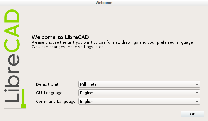
LibreCAD then starts with its default configuration and is ready use. Additional configuration as required can be completed by changing the Application Preferences as shown below.
User Interface
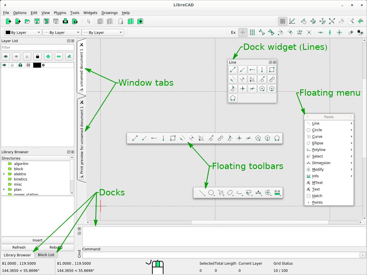
The user interface consists of several major elements:
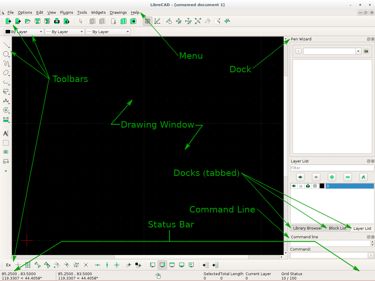
LibreCAD’s default applications window
- Menu: provides access to application functions (open, close, etc.) and drawing tools. Menus can be customized to suit user preferences. Refer to Application Menu in the Reference section.
- Toolbars: provides access to drawing tools and functions. Refer to Toolbars.
- Docks: provides access to drawing tools and functions. Refer to Docks.
- Status bar: displays information about current drawing operation. (See below.)
- Drawing window: displays the active drawing.
Status Bar
There are five sections in the status bar. Those sections displays information about current drawing operation and include coordinates, prompts for the next action, information about the selected entity or entities, and the grid status.
| Section | Description |
|---|---|
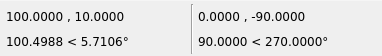
| Coordinates | Displays the absolute coordinates (left) and the relative coordinates (right) of the cross-hair / cursor. Cartesian coordinates are shown on top and and polar coordinates are bottom. Refer to Coordinates in Fundamentals of the Reference section for more details on the type of coordinates.
|
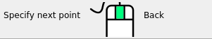
| Next Action | Displays a prompt for the next action required for the current command; e.g. ”Specify next point”, ”Specify center”, etc. Prompts to the left of the mouse icon represent left mouse button actions and the right represent right mouse button actions. |
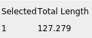
| Selected | Display the total number and the combined lengths of one or more selected entities. |
| Current Layer | Displays the active layer. Refer to Layers in Fundamentals of the Reference section for more details. |
| Grid | Displays the minor and major grid spacing for the X and Y axes. Minor grid spacing is represented by dots, and the major by dotted lines. |
Layout
LibreCAD’s layout and appearance is highly configurable:
- Menus: drop down from the menu bar or can be “torn off” and float anywhere on the display. Click the dashed line at the top of a menu to detach it.
- Toolbars: can be dragged and dropped to the top, bottom, left, right, or float anywhere on the display.
- Docks Widgets: (e.g. command line or layer list) can also be dragged and dropped to the top, bottom, left, right, or float within the drawing window. In addition they can be stacked in the same region of the application window where they will be “tabbed”. Optionally docks can be placed outside of the application window, such as when using multiple monitors. Drawing tools are also available as dock widgets, but are suited as floating “toolboxes”. Widgets can also be resized by dragging their edges.
- Style sheets: allow users to change the visual elements of the application’s window decorations; title bars, fonts, colors, etc. Refer to the Customizing in the Reference section for more details.
LibreCAD applications window - custom layout
Application Preferences
In addition to the layout, LibreCAD has many preferences that will change other aspects of the appearance or behavior of the application. The preferences can be configured by selecting Options -> Application Preferences. Different elements of the preferences can be set; Appearance, Paths and Defaults.
Appearance
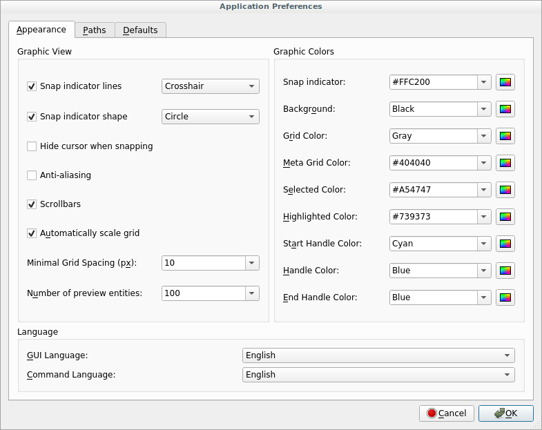
There are three categories on the “Appearance” tab that allows the user to change the look and behavior of LibreCAD.
The Graphic View category has options for the snap indicator style and shape, scroll-bars and grid. Use the Snap Indicator Lines to select the style for orthogonal (Crosshair, Crosshair 2 or Spiderweb) or isometric (Isometric) projections. The Anti-alias setting, if supported by the hardware, when checked will reduce jagged edges of diagonal lines, circles, etc.
The Language categories allows the the user to select the language used in the GUI and command line. Supported languages can be found in the appendix.
Thirdly, the Graphic Colors section allow custom colors to be selected for the snap indicator, drawing background, grid, and other indicators (selections, highlighted items and Handles). Users can select predefined colors from the drop down menu or select their own from the color selector.

Path

The Path tab allows users to specify the directory paths to additional resources; language (“Translations”) and user created or installed Hatch Patterns, Fonts, Parts libraries and Templates and a “Variable file”. These paths do not override the defaults paths, but are appended so the default resources are still available.
It is recommended that user defined resource be placed in a user directory (e.g. home directory on Linux: ~/LibreCAD/Translations, etc.)
- Translations: Language files for the GUI and / or command languages.
- Hatch Patterns, Fonts, Parts Libraries: user created or obtained from other sources such as the Parts Library wiki
- Template: specify the full path and filename of a user-defined drawing template to load when launching the application or starting a new drawing
- Variable File: load a user-defined variable file when starting the application (see the Command Line guide for details on using commands / variables files.)
Defaults
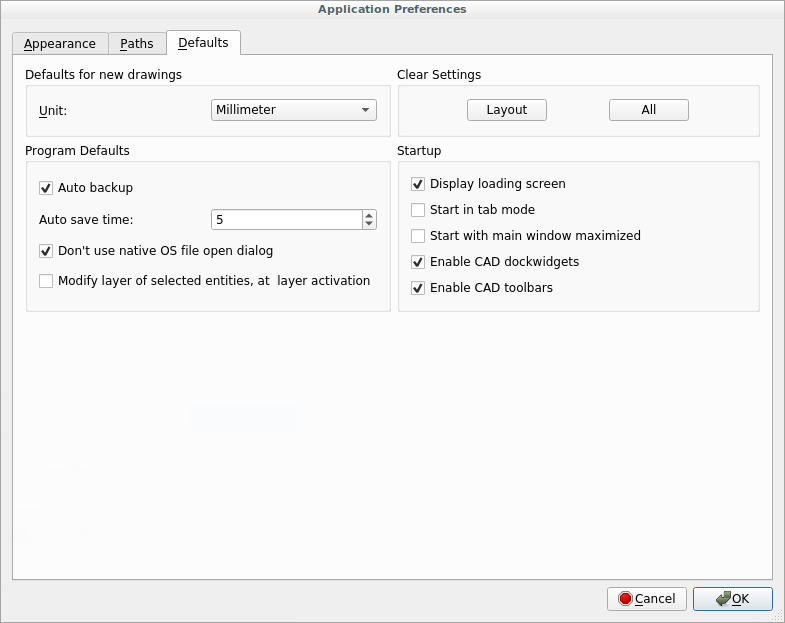
The Defaults tab allows users to specify application-wide defaults.
Drawing Defaults
Unit: Defines the default unit of measure for all new drawings. The default can be overridden by setting the unit of measure in the Drawing preferences or template.
Program Defaults
- Auto backup: When checked, a backup will be created when closing the file. Backup files are saved to the same directory as the drawing file with a tilde (~) appended to the file name.
- Auto save time: The time in minutes to perform an automatic save of the open files. Auto files are saved to the same directory as the drawing file with a hash symbol (#) prefixed to the file name.
- Don’t use native OS file open dialog: When checked, LibreCAD’s file open dialog is displayed when opening files.
- Modify layer of selected entities, at layer activation: If checked, entities can be assigned to a layer by selecting the entities and then selecting the destination layer.
Clear Settings
LibreCAD’s configuration can be partially or entirely reset back to a defaults:
- Layout: Resets the application window layout to the default configuration.
- All: Resets the application to the default configuration. Window layout, color settings, custom menus and toolbars, etc. are all reset. The “Welcome” dialog will be displayed next time the application is launched.
Startup
When checked the following items will:
- Display loading screen: LibreCAD’s load screen (e.g. splash screen) is displayed when launching the application.
- Start in tab mode: the drawing window is tabbed (same as selecting Drawings -> Tab mode from the main menu).
- Start with main window maximized: LibreCAD will start with the application window full screen.
- Enable CAD dockwidgets: show drawing tools (Circle, Curve, etc.) in the widget menu (Widgets -> Dockwidgets)
- Enable CAD toolbars: show drawing tools (Circle, Curve, etc.) in the toolbar menu (Widgets -> Toolbars)